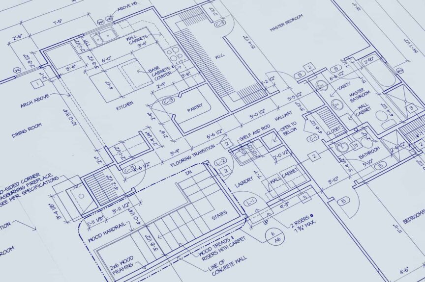
Floor plans are one of the most referenced diagrams in a set of architectural drawings. They are the starting point for understanding the design intent of a home or other building structure. Various types of plans are often included in a drawing set, but for this article, we will use the construction floor plan as a point of reference since it is the most common.
Floor plans typically include the location of walls, both interior and exterior, wall openings such as doors and windows, vertical circulation including stairs, the location of structural elements such as columns, fixture locations including sinks, toilets, attached cabinetry, dimensions, reference symbols, and notes and legends. In addition, the scale of the drawing, title and number, and orientation relative to North-South is included for additional reference.
Apart from the information that can be gathered from the floor plan itself, the drawing also serves as a reference point for other drawings and more detailed information. When viewing a set of drawings, it’s usually a good idea to start with the floor plans to get a general idea of the size and scope of the project and then study the referenced drawings in more detail to establish a more complete understanding. Keep reading as we’ll cover these items in greater detail.
Wall Locations
While floor plans include many elements, wall location is one of the most important organizing factors in a drawing. The location of the exterior walls establishes the overall dimensions of the building. The location of the interior walls determines the sizes of internal rooms and other spaces.
We can think of a plan as a diagram showing a series of spaces and their relationship to one another, defined by the location, size, and orientation of their surrounding walls. These enclosed spaces may include rooms such as bedrooms, bathrooms, living rooms, kitchens, dining rooms, closets, and other miscellaneous rooms specific to the program.
Exterior Walls
Exterior Walls outline the periphery of a house plan. They establish the outer boundaries and limitations within which the interior walls are placed. Exterior walls are typically thicker than interior walls since they need to be structurally more robust and provide insulation and weather control to protect the interior environment. Depending on the building type and size, they can vary from 8 inches to 1′-6″ in width.
Openings such as windows and doors are shown on the exterior walls. In some cases, exterior finish materials, such as brick, stone, metal panel, etc, are also shown on the floor plan, though the level of detail tends to be intentionally limited because the scale of the drawing makes it difficult to read. This level of detail is usually left to the detail plan drawings or wall sections, which are illustrated at a much larger scale. Exterior walls are generally hatched or “poched” in a solid color to make them stand out.
Interior Walls
Interior walls are instrumental in defining the rooms and spaces inside a building. Like exterior walls, they illustrate openings as well as door locations. Because they are usually not insulated and have thinner finishes, they are not as thick as exterior walls. Like exterior walls, interior walls are typically hatched or “poched” to help them read better graphically.
Typical finishes for interior walls include gypsum board (drywall), plaster, wood paneling, thin brick, etc. While drywall is factored into the thickness of interior walls, other finishes are generally not included. The layout of interior walls establishes the link and flow of spaces from one room to another.
Wall Openings
The term wall opening refers to portions of a wall with an interruption, either due to a break in the horizontal plane or intentionally carved out of the wall. They can be either full height from floor to ceiling or only partial height.
Wall openings between rooms are usually designated with a dashed line and no fill (poche) to indicate that there is a transom above the opening. Wall openings also include windows or doors to the exterior and doors between rooms and other spaces.
Windows
Floor plans help identify the location of windows and other glass openings. To emphasize the distinction between a solid wall and a window, the walls are often hatched or “poched” in a solid color, while the windows or other openings are illustrated as a single or double line within a frame.
Though not required, the jambs of the windows are sometimes shown on the ends and the sill is often also illustrated, though they are shown at a minimal level of detail. Because a higher level of detail is reserved for enlarged plan details and wall sections, there is no need to show too much detail on the floor plans. The rough opening of the window is dimensioned on the floor plan.
Doors
Door locations are shown on floor plans, both on interior and exterior walls. The direction of the door swing is important and floor plans provide helpful information on this. The rough opening of the door frame is typically dimensioned in plan and jambs are sometimes shown, though not required.
Door sizes can vary depending on their intended use. Exterior doors tend to be larger than interior doors, and closet doors are typically smaller than the doors of rooms. If a structure is being designed to meet accessibility guidelines for wheelchairs, a 3’-0” wide door is required to provide a minimum clear width of 32” (813 mm) from the face of the door to the stop when open 90 degrees.
Vertical Circulation
Vertical circulation, as the name implies, is any circulation that affects movement in a vertical direction from one level to another. This can be a stair that leads from one floor to another or a simple level change on the same floor. Elevators and escalators, used primarily in commercial settings, are also considered a form of vertical circulation.
Floor plans help to illustrate valuable information regarding vertical circulation, including the location of stairs, general configuration, direction up or down, number of treads, and railing information, among other things. These details are usually illustrated with specific symbols, such as graphic arrows or numbers next to the stairs or other forms of vertical circulation.
Structural Elements
Floor plans help provide useful information on the location of columns and other structural elements. Floor plans show the structural members as well as the overall dimensions between them. This is sometimes further organized using a grid and numbering system to identify each column.
While both architectural and structural floor plans typically include this information, architectural plans also show information regarding the finishes around the structural elements and fireproofing information when required. This level of information is more common in commercial building floor plans. However, residential floor plans sometimes also include these details.
Fixture Locations
Wall-attached fixtures, such as cabinets and shelving, are shown on floor plans. Floor-mounted fixtures such as kitchen islands and plumbing fixtures such as sinks and toilets are also included on the floor plan drawings. Built-in appliances are included as well. Construction floor plans do not typically include electrical fixtures. However, they are included in the electrical floor plans.
Heating fixtures such as radiators, water heaters, and chimneys are sometimes shown on floor plans. Fixtures help identify the room’s use and provide the contractor or design consultant with information on the fixture type and location. A kitchen, for example, can easily be identified by the cabinetry, cooking equipment, and plumbing fixtures illustrated on the plan.
Dimensions
One of the most essential pieces of information that floor plans provide is the dimensions of the various components on the plan. The overall extents of a building are dimensioned along the exterior walls and all openings such as windows and doors are as well. Interior room dimensions are also shown on floor plans.
Wall dimensions are measured from the face of walls to show the clear distance. Exterior wall dimensions are taken from the outside face of the wall, while interior dimensions are taken from the inside (interior) face of the wall. Dimensions are also shown in a hierarchical order so that more detailed dimensions are shown closer to the building while overall dimensions are shown further away from the building plan.
Reference Symbols
Reference symbols are an essential source of information on floor plans since they refer the user to more detailed information. Elevation symbols – usually represented by a circle with an arrow pointing in a specific direction – reference the exterior and interior elevation (straight-on view of walls and openings) drawings.
Detailed wall sections are also referenced by section symbols on floor plans. These symbols are typically shown as a line “cut” with a reference number and sheet number in a circle with an arrow pointing in the direction of the cut. On the opposite end is a “flag” indicating the direction of the cut.
Additional symbols on plans include door and window identifications and wall type identifications which are referenced to either notes and legends or more detailed drawings. Detail call-outs are also typically indicated on floor plans and usually illustrated as a dashed rectangular line with rounded edges and a reference number to both the specific drawing and the sheet within the drawing set where they can be located.
Notes and Legends
Notes and legends complete the information provided on the floor plans by providing either more detailed written information or descriptions of the symbols used on the plans. When reviewing floor plans, it’s crucial to reference these notes and legends as they will contain important information that cannot be directly illustrated on the plan.
Notes commonly shown on the floor plans include general notes to the contractor, structural notes related to the plans, and additional information regarding the symbols used on the plan, including reference to other drawings or specifications. Often information on member sizes, material types, and typical spacing is included in these notes.
Drawing Number and Description
To identify specific drawings on the page and when used for reference on other pages, numbers are used for each drawing on a page. A description is included as well for additional reference. Underneath the description is a scale reference which can be used as a guide for measuring approximate distances where dimensions are not provided.
In addition to the drawing scale, orientation information is provided either on the title sheet or the specific floor plan shown on the sheet. A North arrow is typically used to show either true North or project North, which is an approximation of North relative to the building or floor plan. Sometimes both True North and Project North are included for reference.
Title Block
Finally, as part of a complete drawing set, a floor plan will include a title block with sheet title information, a reference number, scale and orientation, the drawing creation date as well as dates and descriptions of any revisions, and the names of the consultants involved in the design of the project.
In addition to providing important information about the building project, the title block also helps to graphically “frame” the drawing. It also typically provides a spot for the architect or engineer’s seal once the drawings are approved and ready for construction.
Other Types of Floor Plans
So far, we have covered the construction floor plan. However, various other types of floor plans are commonly found in a set of drawings. These include the electrical floor plan, structural floor plan, mechanical floor plan, plumbing floor plan, and enlarged floor plans, among others.
Reflected ceiling plans, while technically not floor plans, are essentially drawn similar to a floor plan with the ceiling above shown “mirrored”. Doors are not shown on reflected ceiling plans, but the transom above is included as a double line. These plans are used to illustrate the location of light fixtures on the ceiling above.
Wrapping Up
Floor plans convey a great deal of information in a single drawing. They help the owner or contractor understand the layout of a home or other building. In addition, they provide dimensional information between the plan’s various components.
Floor plans function as a starting reference point for more detailed drawings. They also serve as a key to schedules and important notes pertaining to building design and construction. This is why floor plans are often the first and most frequently referenced files in a drawing set.
Share this Post
Giovanni Valle is a licensed architect and LEED-accredited professional and is certified by the National Council of Architectural Registration Boards (NCARB). He is the author and managing editor of various digital publications, including BuilderSpace, Your Own Architect, and Interiors Place.